
2. Physical Layer
1. Analog Signals and Digital Signals
Analog Signals
EM waves: wavelength, amplitude, frequency, and Hertz
- Definition: An analog signal is a continuous signal that represents physical measurements. It varies smoothly and continuously over time, often in the form of a sine wave or other continuous waveforms.
- Characteristics:
- Continuous: Can take an infinite number of values within a range.
- Representation: Usually represented as voltage, current, or other measurable physical quantities.
- Examples: Sound waves, temperature readings, and the voltage from a microphone.
- Visual Example: A sound wave is an example of an analog signal, where the wave continuously fluctuates.
Digital Signals
- Definition: A digital signal represents data in a discrete form. It takes specific values (often 0 and 1, representing “off” and “on” states) at distinct time intervals.
- Characteristics:
- Discrete: Takes specific values at fixed intervals of time (e.g., 0 and 1).
- Representation: Often used in digital devices, computers, and data transmission.
- Examples: Binary data (1s and 0s) in computer networks, digital clocks, and digital audio.
- Visual Example: A digital signal typically consists of square waves, where the signal jumps between “high” and “low” states in discrete steps.
1.1 Analog to Digital Conversion (ADC)
Process: The process of converting an analog signal to a digital signal is called Analog-to-Digital Conversion (ADC). It involves sampling the continuous analog signal at regular intervals and then quantizing the sampled values to discrete numbers.
Steps:
- Sampling: The continuous analog signal is sampled at regular intervals (e.g., every 1 millisecond).
- Quantization: Each sampled value is mapped to the nearest discrete value in a set range (e.g., integer values from 0 to 255 for an 8-bit signal).
- Encoding: Each quantized value is then encoded into binary format.
Example
Let’s consider an analog signal that varies continuously between 0 and 5V.
- Sample Rate: We choose to sample the analog signal every 1 ms.
- Quantization: The signal is quantized into 8 bits, meaning we can represent 256 possible values (ranging from 0 to 255).
- Encoding: If the sample taken at 1 ms is 2.5V, the closest value to 2.5V (in a 0-5V range) is 128, which would be represented as
10000000(binary).
Analog Signal (5V) → ADC Samples → Digital Signal (Binary)
1.2 Digital to Analog Conversion (DAC)
Process: The process of converting a digital signal to an analog signal is called Digital-to-Analog Conversion (DAC). It involves reconstructing the continuous analog waveform from a sequence of discrete digital values (usually from binary numbers).
Steps:
- Binary Input: The digital signal is made up of a series of binary values (e.g.,
1101,0110, etc.). - Reconstruction: A DAC reconstructs the analog signal by generating corresponding voltage levels for each binary value and connecting them smoothly.
- Smoothing: In some cases, the output needs to be smoothed (using a filter) to remove jagged edges (aliasing) caused by the discrete nature of the signal.
Example
Let’s consider a simple 4-bit digital signal with values ranging from 0 to 15 (binary values from 0000 to 1111), where each digital value corresponds to a voltage level in a 0–5V range.
- Binary Sequence:
1010(binary) corresponds to10in decimal. - Mapping: Using a DAC, the value
10might map to a voltage of 3.3V on the analog signal. - Output: The DAC outputs a smooth voltage level of 3.3V.
Digital Signal (Binary) → DAC Reconstructs Signal → Analog Signal (Voltage)
1.3 Example Conversions
1. Analog to Digital Conversion (ADC) Example
Consider an analog signal that continuously fluctuates between 0V and 5V. Let’s convert this signal to a digital signal using an ADC.
- Analog Signal: A sine wave oscillating between 0V and 5V.
- Sampling Rate: Let’s say we sample the signal at 1 ms intervals.
- Quantization: Assume we have an 8-bit ADC, meaning the signal can be quantized into 256 levels (values from 0 to 255).
- Process:
- At time 0 ms, the signal is at 0V. This corresponds to the value
0. - At time 1 ms, the signal is at 2.5V. This corresponds to the value
128in the 8-bit range. - At time 2 ms, the signal is at 5V. This corresponds to the value
255.
- At time 0 ms, the signal is at 0V. This corresponds to the value
Thus, the analog signal has been converted into the following digital values:
0V -> 000000002.5V -> 100000005V -> 11111111
2. Digital to Analog Conversion (DAC) Example
Now, let’s convert a digital signal back to analog using a DAC.
- Digital Signal: The digital signal we have is
1101(binary), which corresponds to a decimal value of13. - Mapping: Assume that the DAC is set to map the range 0-15 (4-bit) to 0-5V. So:
13maps to13/15 * 5V ≈ 4.33V.
- DAC Output: The DAC will output a voltage of approximately 4.33V.
2. Digital Signal Encoding
Signal Encoding: Digital Signals
In the context of networking, especially at the physical layer, digital encoding techniques are used to represent data (typically in binary form) as electrical, optical, or radio signals that can be transmitted over a communication medium. These techniques are critical because they help ensure that the transmitted data can be accurately received, decoded, and processed by the receiver.
Some common digital encoding techniques used in the physical layer of networking include:
2.1 Manchester Encoding
- Definition: In Manchester encoding, each bit is represented by a transition in the signal. A logical 1 is represented by a transition from low to high (0 → 1) in the middle of the bit period, and a logical 0 is represented by a transition from high to low (1 → 0).
- Key Feature: The main feature of Manchester encoding is that it ensures there is always a transition in the middle of each bit period, providing clock synchronization.
- Advantages:
- Provides built-in synchronization (no need for a separate clock signal).
- Helps with error detection due to the consistent transitions.
- Disadvantages:
- Requires more bandwidth compared to simple non-return-to-zero encoding schemes.
2.2 Differential Manchester Encoding
- Definition: A variant of Manchester encoding, but the difference is in how the transitions are interpreted. A logical 1 is represented by a transition at the beginning of the bit period, while a logical 0 is represented by no transition at the beginning and a transition at the midpoint.
- Key Feature: The transition at the midpoint of the bit period is used for synchronization, while the state at the start of the period indicates the bit’s value.
- Advantages:
- Like Manchester encoding, it provides synchronization and error detection.
- It is more robust to signal polarity reversals because the transition is used for determining the bit value.
- Disadvantages:
- Still requires more bandwidth than some simpler schemes.
Signal Polity Reversal?
Signal polarity reversal refers to a situation where the polarity (or voltage level) of a signal is flipped or reversed. In digital communication, this usually means that a signal’s positive and negative voltage levels swap places, effectively changing the interpretation of the data being transmitted.
For example, in a typical binary signal:
- A logical 1 might be represented by a positive voltage (e.g., +5V).
- A logical 0 might be represented by a negative voltage (e.g., -5V).
A signal polarity reversal would swap these levels, meaning:
- The logical 1 would now be represented by the negative voltage (e.g., -5V).
- The logical 0 would be represented by the positive voltage (e.g., +5V).
Causes of Signal Polarity Reversal
Signal polarity reversals can occur due to various reasons, such as:
- Transmission Errors: During the transmission of signals, especially over long distances or noisy channels, the signal may get distorted or suffer from phase shifts, causing a reversal in polarity.
- Electrical Interference: Electromagnetic interference (EMI) or other forms of noise in the transmission medium can cause voltage levels to be inverted.
- Equipment Malfunction: If there’s a fault or misconfiguration in the transmitting or receiving equipment (e.g., a malfunctioning cable, amplifier, or signal processor), the signal polarity might get flipped unintentionally.
Impact on Digital Communication
Signal polarity reversal can cause problems in interpreting the transmitted data, as the receiver will think the data is flipped. For example, a logical 1 might be interpreted as a 0, and vice versa.
Handling Polarity Reversals
To address the issue of signal polarity reversal, some encoding schemes and techniques include mechanisms to detect or avoid these problems:
- Differential Encoding: In schemes like Differential Manchester encoding or Alternate Mark Inversion (AMI), data is encoded in such a way that the relative changes in signal polarity matter more than the absolute polarity. For example, in AMI, the logical 1 alternates between positive and negative voltages, so even if there is a polarity reversal, the receiver can still detect the alternating pattern correctly.
MLT-3 (Multilevel Transmit-3) encoding is a line coding scheme used primarily in high-speed digital communication systems to encode binary data for transmission over physical media. It is a multilevel encoding technique that is commonly used in Ethernet, particularly in standards like 100BASE-TX (Fast Ethernet).
2.3 MLT-3 Encoding
MLT-3 Line/Signal Encoding
MLT-3 encoding uses three voltage levels: positive, zero, and negative. Instead of simply representing a binary 1 with a positive voltage and a 0 with zero voltage (as in simpler encoding schemes like NRZ), MLT-3 encodes binary data by changing the signal between three distinct voltage levels:
- +V (positive voltage)
- 0V (zero voltage)
- -V (negative voltage)
Each 1 or 0 in the binary stream is mapped to one of these three levels, with the key difference being that the signal doesn’t stay at the same voltage level for consecutive 1s or 0s. The voltage level alternates after each transmission of data.
Key Rules of MLT-3 Encoding
- Logical 1 (1 bit): A logical 1 causes the signal to transition to the next level (positive, zero, or negative), with each new 1 bit causing the signal to switch between these three levels in a cyclic manner.
- Logical 0 (0 bit): A logical 0 causes no transition in the signal, meaning the signal stays at the same voltage level.
So the transitions occur only when a 1 bit is encountered. A string of consecutive 0s will leave the signal at the same level without any changes.
For example:
- If the previous signal level was 0V and the next bit is a 1, the signal will go to either +V or -V, depending on where it is in the cycle.
- If the next bit is a 0, the signal stays at the current level (no transition).
The sequence of voltage levels for a data stream would look like this:
- Initial state: 0V
- Bit stream: 1 → transition to +V
- Bit stream: 0 → stay at +V
- Bit stream: 1 → transition to 0V
- Bit stream: 0 → stay at 0V
- Bit stream: 1 → transition to -V
- Bit stream: 0 → stay at -V
- Bit stream: 1 → transition to +V … and so on.
Why Use MLT-3?
MLT-3 encoding is particularly effective for high-speed data transmission because it reduces the DC component (the long-term average voltage) and requires less bandwidth than simpler schemes like NRZ. The key advantages are:
- Reduced Signal Power: By limiting the number of transitions (since only 1s cause a voltage change), MLT-3 reduces the signal’s power consumption and electromagnetic interference (EMI), making it more efficient for high-speed transmissions.
- Clock Recovery: MLT-3 helps with clock synchronization, as there are enough transitions in the signal to allow the receiver to recover the clock from the signal itself.
- Reduced Frequency Spectrum Usage: Since the signal doesn’t continuously switch between high and low voltages, MLT-3 generally requires less bandwidth compared to other encoding schemes, which is crucial for high-speed Ethernet transmission.
Advantages of MLT-3 Encoding
- Efficient Bandwidth Usage: Compared to other encoding schemes like NRZ, MLT-3 requires less bandwidth, making it ideal for high-speed communications (e.g., Ethernet).
- Fewer Transitions: This leads to lower electromagnetic interference (EMI), which helps with signal integrity over longer distances.
- Reduced DC Bias: MLT-3 encoding helps eliminate any long-term DC component (average voltage), which could interfere with the transmission.
Disadvantages of MLT-3 Encoding
- More Complex: MLT-3 encoding is more complex to implement compared to simpler encoding techniques like NRZ.
- Limited Transitions: Since only 1s cause transitions, long sequences of 0s could result in no voltage transitions for a while, which might cause synchronization issues over long periods without changes.
Where MLT-3 is Used
MLT-3 is used in high-speed Ethernet standards such as:
- 100BASE-TX: This is the Fast Ethernet standard that uses MLT-3 encoding for data transmission over twisted-pair copper cables.
- Other High-Speed Networks: It’s sometimes used in other high-speed serial communication protocols that require efficient bandwidth usage.
3. Terminology
Terminology
3.1 Bandwidth
- Definition: Bandwidth refers to the maximum capacity of a network connection to transmit data over a specific period, typically measured in bits per second (bps) or its higher units like Mbps (megabits per second) or Gbps (gigabits per second).
- Concept: It’s essentially the “width” of the communication channel and represents how much data can be sent at once, like the width of a pipe that dictates how much water (data) can flow through it.
3.2 Lag / Latency
- Definition: Lag refers to the delay or latency in a network. It’s the time it takes for data to travel from the source to the destination and back (round-trip time).
- Concept: Lag can affect real-time activities like online gaming or video conferencing, where even small delays can be noticeable. It’s typically measured in milliseconds (ms).
3.3 Speed
- Definition: Speed refers to how fast data moves across the network. It can be thought of as the time it takes for data to travel from the sender to the receiver.
- Measurement: Often measured in milliseconds (ms) for latency (the time it takes for a packet to travel one way from source to destination), or in terms of Mbps/Gbps when referring to download/upload speeds.
- Focus: Speed emphasizes the responsiveness of the network. It’s commonly used in the context of ping times or the delay experienced in activities like gaming, video calls, or browsing.
3.4 Throughput
- Definition: Throughput is the actual rate at which data is successfully transferred over the network. It’s the effective data transfer rate, accounting for all factors influencing the transfer.
- Measurement: Typically measured in Mbps or Gbps, and is the actual amount of data successfully transferred over a period (e.g., data sent in 1 second).
- Focus: Throughput reflects the real-world performance of the network and can be influenced by factors like congestion, protocol overhead, signal interference, or network errors.
3.5 Key Differences:
- Speed is more about how fast data can travel or be received (response time), whereas throughput measures how much data is successfully transferred over time.
- Speed can refer to both latency (how long it takes) and bandwidth (how much can be transferred), while throughput is specifically the actual transferred data rate.
Example
- Speed: If you’re downloading a file, speed might be the time it takes for the first part of the file to appear on your computer (latency) or the rate at which it starts downloading (bandwidth).
- Throughput: The total amount of data downloaded successfully over time — for example, you might see 50 Mbps throughput when your download finishes.
4 Baseband vs Broadband
Baseband vs Broadband
Baseband and Broadband refer to different types of signal transmission techniques used in networking and communication systems. Here’s how they differ:
4.1 Baseband
- Definition: Baseband refers to a transmission method where a single signal occupies the entire bandwidth of the communication medium. In baseband transmission, the signal is transmitted in its original form, without modulation or division into multiple frequencies.
- Characteristics:
- Single Channel: Only one signal is transmitted at a time, meaning the entire bandwidth is dedicated to that single transmission.
- Lower Data Rates: Since only one signal is sent at a time, baseband transmission typically offers lower data rates compared to broadband.
- Example: Ethernet (IEEE 802.3) and digital audio/video transmission over a single cable (like HDMI).
- Use: Baseband is commonly used in local area networks (LANs) and other applications where only one signal needs to be transmitted at a time, such as in wired computer networks.
4.2 Broadband
- Definition: Broadband refers to the use of a wide range of frequencies to transmit multiple signals simultaneously. In broadband transmission, multiple data channels are sent at the same time, each using a different frequency.
- Characteristics:
- Multiple Channels: Broadband can carry several signals over the same medium by dividing the spectrum into multiple frequency bands.
- Higher Data Rates: Due to the use of a wide frequency spectrum, broadband can support high data transfer rates.
- Example: Cable Internet, DSL (Digital Subscriber Line), and Wi-Fi are examples of broadband technologies.
- Use: Primarily used for high-speed data, voice, and video transmission, allowing multiple signals to travel simultaneously over the same line (like for internet, TV, and telephone services).
4.3 Key Differences
-
Signal Transmission:
- Broadband: Multiple signals are transmitted simultaneously over different frequencies.
- Baseband: Only a single signal is transmitted at a time over the full available bandwidth.
-
Bandwidth Usage:
- Broadband: Utilizes a wide range of frequencies, allowing for higher data rates and multiple services (e.g., voice, video, and data).
- Baseband: Uses the full available bandwidth for just one signal, often resulting in lower data transfer rates.
-
Examples:
- Broadband: Cable Internet, DSL, fiber-optic, Wi-Fi.
- Baseband: Ethernet (LAN), serial communication, traditional telephones.
5. Transmission Mediums and Modes
5.1 Wired Mediums
1. Ethernet Cable
An Ethernet cable is a type of network cable used to connect devices in a local area network (LAN) or to link devices to a router or modem for Internet access. These cables carry data in the form of electrical signals and allow devices to communicate with each other over a wired network. Ethernet cables are commonly used in networking applications for desktops, laptops, routers, switches, and other devices.
Cat5? Cat6? Cat7?
Ethernet cables typically come in different categories (Cat5e, Cat6, Cat6a, Cat7, etc.), which indicate their performance and speed capabilities. For instance:
- Cat5e supports speeds up to 1 Gbps.
- Cat6 can handle speeds up to 10 Gbps for shorter distances.
- Cat6a and higher categories support even faster speeds and higher bandwidth.
Different Configuration Modes for Ethernet Cables:
Ethernet cables can be wired in different configuration modes to support various networking needs. These modes are related to the way the wires are arranged inside the cable:
-
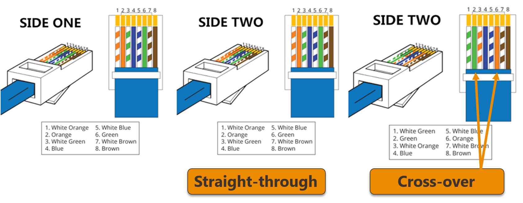
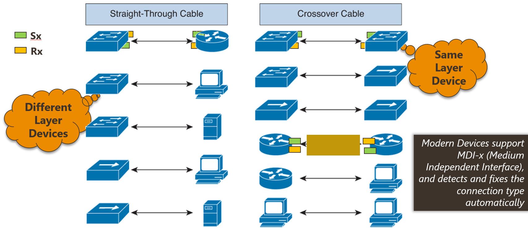
Straight-Through Cable:
- This is the most common Ethernet cable configuration. Both ends of the cable are wired in the same way (using the same color code).
- It is typically used to connect different types of devices (e.g., computer to a switch or router).
- The standard wiring scheme used is:
- T568A or T568B wiring standards.
- Pinout:
- Pin 1: White with green stripes
- Pin 2: Green
- Pin 3: White with orange stripes
- Pin 4: Blue
- Pin 5: White with blue stripes
- Pin 6: Orange
- Pin 7: White with brown stripes
- Pin 8: Brown
-
Crossover Cable:
- In a crossover cable, one end is wired as a straight-through cable and the other end is wired as a reversed version of it. This is useful for directly connecting similar devices (e.g., computer to computer, switch to switch).
- This configuration crosses the transmit and receive signals so that they align correctly between devices.
- Standard wiring for crossover cables:
- Pin 1: White with green stripes (end 1)
- Pin 2: Green (end 1)
- Pin 3: White with orange stripes (end 2)
- Pin 4: Blue (end 2)
- Pin 5: White with blue stripes (end 2)
- Pin 6: Orange (end 2)
- Pin 7: White with brown stripes (end 1)
- Pin 8: Brown (end 1)
-
Rolled Cable:
- A rolled cable is generally used for special purposes and is the least common configuration.
- It connects two devices in a manner where the pinouts at both ends of the cable are reversed (similar to a crossover cable but often used for serial communication or console ports on network devices like routers and switches).
T568A vs. T568B:
When creating Ethernet cables, the two main wiring standards are T568A and T568B. Both are similar, with the primary difference being the order of the colored wire pairs.
-
T568A:
- Pin 1: White with green stripes
- Pin 2: Green
- Pin 3: White with orange stripes
- Pin 4: Blue
- Pin 5: White with blue stripes
- Pin 6: Orange
- Pin 7: White with brown stripes
- Pin 8: Brown
-
T568B:
- Pin 1: White with orange stripes
- Pin 2: Orange
- Pin 3: White with green stripes
- Pin 4: Blue
- Pin 5: White with blue stripes
- Pin 6: Green
- Pin 7: White with brown stripes
- Pin 8: Brown
MDI-X Protocol
In modern-day networks, the configuration of Ethernet cables (i.e., whether they are straight-through or crossover) does matter less due to the MDX (Medium Dependent Interface Crossover) protocol, which is commonly implemented in most modern networking devices.
What is MDX (MDI-X)?
MDI-X stands for Medium Dependent Interface Crossover, and it is a technology implemented in most modern Ethernet devices such as network cards, routers, switches, and hubs. MDI-X allows the device to automatically detect whether it needs to use a straight-through or crossover cable for a connection.
In other words, MDI-X automatically “reverses” the transmit and receive pairs as needed, which makes it unnecessary to manually select between straight-through or crossover cables when connecting similar devices (e.g., computer to computer, switch to switch). This feature is typically found in modern switches and routers.
How MDX Affects Cable Configuration:
- With MDX-enabled devices, you can use a straight-through Ethernet cable to connect devices that would traditionally require a crossover cable.
- The devices will automatically detect the connection type and adjust the transmission and reception of data accordingly. This means that the devices handle the crossover internally, without needing a special cable configuration.
For example:
- If you’re connecting a computer to a router or a switch to a modem, you can use a straight-through cable, and the devices will manage the wiring configuration automatically.
- If you’re connecting two computers directly or two switches without MDX support, a crossover cable would still be necessary unless you have MDX-enabled devices.
Does Cable Configuration Matter Anymore?
- For most modern networking setups, especially with switches, routers, and modern computers, the configuration of the cable (straight-through vs. crossover) matters less because of the automatic crossover functionality (MDI-X).
- However, older devices or devices without MDX may still require crossover cables when directly connecting similar devices (like computer-to-computer or switch-to-switch) that do not automatically handle the crossover internally.
2. Fiber Optics
Fiber Optics
Optical fiber cables are a type of high-speed data transmission medium that use light to carry information over long distances with minimal loss. Here’s a breakdown of how they work:
Structure of Optical Fiber Cables
- Core: The innermost part of the fiber, made of glass or plastic, where light travels. It has a high refractive index.
- Cladding: A layer surrounding the core, made of material with a lower refractive index. It keeps light within the core through total internal reflection.
- Buffer Coating: A protective layer (usually plastic) that shields the core and cladding from damage and moisture.
Principle of Operation
- Total Internal Reflection: Light signals are transmitted through the core by bouncing off the cladding. Because the core has a higher refractive index than the cladding, light is reflected back into the core instead of escaping, allowing it to travel long distances.
- Light Source: A laser or LED generates light pulses that encode data (binary 1s and 0s).
- Signal Propagation: The light pulses travel through the core, maintaining their integrity over long distances due to the low attenuation of the fiber material.
Types of Optical Fibers
- Single-Mode Fiber: Has a small core (about 9 µm) and allows only one mode of light to propagate. It is used for long-distance communication due to low signal loss.
- Multimode Fiber: Has a larger core (about 50-62.5 µm) and allows multiple light modes to propagate. It is used for shorter distances, such as within buildings or campuses.
Advantages of Optical Fiber Cables
- High Bandwidth: Can carry large amounts of data at very high speeds.
- Low Attenuation: Signals can travel long distances without significant loss.
- Immunity to Interference: Unlike copper cables, fiber optics are not affected by electromagnetic interference.
- Security: Difficult to tap into without detection, making them more secure for data transmission.
Applications
- Telecommunications: Used in internet, phone, and cable TV networks.
- Medical Imaging: Used in endoscopes and other imaging devices.
- Industrial and Military: For secure and reliable communication in harsh environments.
Challenges
- Fragility: Optical fibers are more delicate than copper wires and require careful handling.
- Cost: Initial installation can be expensive, though long-term benefits often outweigh the costs.
5.2 Wireless Mediums
EM spectrum
The electromagnetic (EM) spectrum is the range of all types of electromagnetic radiation, which is energy that travels in waves. It includes everything from radio waves to gamma rays, categorized by their wavelength and frequency. Here’s a breakdown of the major regions of the EM spectrum:
1. Radio Waves
- Wavelength: Longest wavelengths (1 mm to 100 km).
- Frequency: Lowest frequencies (3 kHz to 300 GHz).
- Uses: Communication (radio, TV, mobile phones), radar, and astronomy.
- Properties: Can travel long distances and penetrate through walls and obstacles.
2. Microwaves
- Wavelength: 1 mm to 1 m.
- Frequency: 300 MHz to 300 GHz.
- Uses: Microwave ovens, satellite communication, Wi-Fi, and radar.
- Properties: Absorbed by water, making them effective for heating food.
3. Infrared (IR)
- Wavelength: 700 nm to 1 mm.
- Frequency: 300 GHz to 430 THz.
- Uses: Remote controls, thermal imaging, night vision, and heat sensors.
- Properties: Emitted by warm objects; felt as heat.
4. Visible Light
- Wavelength: 400 nm to 700 nm.
- Frequency: 430 THz to 750 THz.
- Uses: Human vision, photography, and optical communication.
- Properties: The only part of the spectrum visible to the human eye. It consists of colors ranging from violet (shorter wavelength) to red (longer wavelength).
5. Ultraviolet (UV)
- Wavelength: 10 nm to 400 nm.
- Frequency: 750 THz to 30 PHz.
- Uses: Sterilization, black lights, and medical imaging.
- Properties: Can cause sunburn and skin damage; absorbed by the ozone layer.
6. X-Rays
- Wavelength: 0.01 nm to 10 nm.
- Frequency: 30 PHz to 30 EHz.
- Uses: Medical imaging (e.g., X-ray scans), security screening, and astronomy.
- Properties: Penetrate soft tissues but are absorbed by denser materials like bones.
7. Gamma Rays
- Wavelength: Shortest wavelengths (less than 0.01 nm).
- Frequency: Highest frequencies (above 30 EHz).
- Uses: Cancer treatment (radiation therapy), sterilization, and astrophysics.
- Properties: Highly penetrating and energetic; produced by nuclear reactions and cosmic events.
Wireless Signal Attenuation
Wi-Fi signals: Attenuation
Wireless signal attenuation refers to the reduction in the strength of a wireless signal as it propagates through a medium or encounters obstacles. This weakening of the signal can affect the quality and reliability of wireless communication. Attenuation is a natural phenomenon and occurs due to various factors, including distance, interference, and physical barriers.
Causes of Wireless Signal Attenuation
-
Distance:
- Wireless signals weaken as they travel farther from the source. This is due to the inverse-square law, which states that signal strength decreases proportionally to the square of the distance from the transmitter.
-
Obstacles:
- Physical barriers like walls, buildings, trees, and furniture can absorb or reflect wireless signals, causing attenuation. Different materials attenuate signals to varying degrees:
- Metals: Highly reflective, causing significant signal loss.
- Concrete and Brick: Absorb and block signals.
- Glass and Wood: Cause moderate attenuation.
- Physical barriers like walls, buildings, trees, and furniture can absorb or reflect wireless signals, causing attenuation. Different materials attenuate signals to varying degrees:
-
Interference:
- Other wireless devices operating on the same or nearby frequencies (e.g., Wi-Fi, Bluetooth, microwaves) can cause interference, leading to signal degradation.
-
Environmental Factors:
- Weather conditions like rain, fog, or snow can attenuate signals, especially in higher-frequency bands (e.g., 5 GHz or millimeter waves).
- Atmospheric absorption can also affect certain frequencies.
-
Frequency of the Signal:
- Higher-frequency signals (e.g., 5 GHz Wi-Fi) attenuate more quickly over distance and are more easily blocked by obstacles compared to lower-frequency signals (e.g., 2.4 GHz Wi-Fi).
Effects of Attenuation
- Reduced Signal Strength: The signal becomes weaker, making it harder for the receiver to detect and decode the information.
- Lower Data Rates: Attenuation can lead to slower data transmission speeds.
- Increased Errors: Weak signals are more prone to noise and interference, resulting in data errors or packet loss.
- Limited Range: Attenuation limits the effective range of wireless communication.
Mitigating Wireless Signal Attenuation
-
Use of Repeaters or Extenders:
- Devices like Wi-Fi repeaters or range extenders can amplify and retransmit signals to cover larger areas.
-
Antenna Optimization:
- Using directional antennas can focus the signal in a specific direction, reducing attenuation in that path.
-
Frequency Selection:
- Lower-frequency signals (e.g., 2.4 GHz) are less prone to attenuation and can travel farther than higher-frequency signals (e.g., 5 GHz).
-
Reducing Obstacles:
- Positioning routers and devices to minimize physical barriers can improve signal strength.
-
Signal Amplification:
- Using amplifiers or higher-power transmitters can boost signal strength.
-
Mesh Networks:
- Deploying multiple interconnected access points can ensure consistent coverage over a large area.
5.3 Transmission Modes
Simplex, half duplex, and full duplex
Transmission modes describe the direction of data flow between two devices in a communication system. There are several types of transmission modes, including Simplex, Half-Duplex, and Full-Duplex. Here’s a breakdown of these modes:
1. Simplex
-
Definition: In simplex mode, data flows in only one direction—from the sender to the receiver. There is no feedback or communication in the opposite direction.
-
Example: Radio and TV broadcasting are examples of simplex communication, where information is sent from the broadcaster to the audience, but the audience cannot send data back to the broadcaster.
-
Characteristics:
- One-way communication.
- Used in applications where the receiver does not need to send any information back.
- Efficient for broadcasting.
2. Half-Duplex
-
Definition: In half-duplex mode, data can flow in both directions, but not at the same time. The transmission is bi-directional, but the devices must alternate between sending and receiving.
-
Example: Walkie-talkies are a common example of half-duplex communication. When one person talks, the other must listen, and they can switch roles but not simultaneously communicate.
-
Characteristics:
- Two-way communication, but not simultaneous.
- Communication happens in turns (one device sends, then the other sends).
- More efficient than simplex for situations needing two-way communication but not continuous transmission.
3. Full-Duplex
-
Definition: In full-duplex mode, data can flow in both directions simultaneously. Both devices can send and receive data at the same time, enabling continuous two-way communication.
-
Example: Telephone calls and modern internet communications (e.g., video conferencing, VoIP) use full-duplex transmission, where both parties can speak and hear each other at the same time.
-
Characteristics:
- Two-way communication, simultaneous transmission and reception.
- More complex and requires additional resources like separate channels for sending and receiving.
- Most modern communication systems (such as cellular networks and broadband internet) use full-duplex.
6. Last Mile Technologies
Last Mile refers to the final leg of the telecommunications or networking infrastructure that connects the service provider’s network to the end user’s premises (e.g., a home, office, or business). The “last mile” is often the most challenging and expensive part of delivering services like internet access, telephone lines, or cable TV to customers.
Last Mile Technologies are the solutions and technologies used to deliver services from the provider’s central network infrastructure to the end users. These technologies can vary based on factors like geographic location, population density, and the type of service being delivered.
6.1 DSL (Digital Subscriber Line):
Last Mile Technologies
- Description: DSL uses existing copper telephone lines to deliver high-speed internet to homes and businesses.
- Speed: Typically ranges from 1 Mbps to 100 Mbps, depending on the specific DSL technology (e.g., ADSL, VDSL).
- Limitations: Speed decreases with the distance from the telephone exchange.
6.2 Cellular Networks / What is 5G
5G stands for fifth-generation mobile network technology, which is the latest upgrade in the series of cellular networks, following 4G (LTE). It is designed to provide faster speeds, lower latency, and more reliable connectivity than previous generations, supporting a wide range of new and emerging technologies.
6.2.1 Key Features of 5G
-
Faster Speeds:
- 5G offers significantly faster speeds compared to 4G. It can provide download speeds of up to 10 Gbps (compared to 4G’s 1 Gbps), enabling rapid access to large files, videos, and high-definition content.
- This speed enables applications like 4K video streaming, AR/VR (augmented reality/virtual reality), and high-definition video calls to be more seamless.
-
Low Latency:
- Latency is the time it takes for data to travel from one point to another. 5G promises ultra-low latency, reducing it to as low as 1 millisecond (ms), compared to 30-50 ms in 4G networks.
- Low latency is crucial for applications that require near-instantaneous communication, such as autonomous vehicles, remote surgery, and industrial automation.
-
Massive Connectivity:
- 5G is designed to handle a vast number of connected devices simultaneously. This feature is especially important with the rise of the Internet of Things (IoT), where billions of devices such as smart home devices, wearables, and sensors are connected.
- 5G networks can support up to 1 million devices per square kilometer, enabling smart cities, smart grids, and other IoT-driven ecosystems.
-
Network Slicing:
- Network slicing is a technology that allows operators to create multiple virtual networks within a single physical 5G network. Each slice can be customized to meet specific requirements, such as speed, latency, or reliability.
- This flexibility enables different use cases (e.g., public safety, automotive, healthcare) to operate efficiently on the same infrastructure, without interference.
-
Enhanced Capacity:
- 5G has much more spectral capacity than 4G, meaning it can handle more data traffic. It operates in new frequency bands, including millimeter-wave (24 GHz and above) bands, allowing for greater bandwidth and higher data rates.
-
Improved Energy Efficiency:
- 5G is designed to be more energy-efficient compared to 4G, especially for IoT devices, which need to operate with minimal power consumption. This efficiency extends to both the user devices and the network infrastructure.
6.2.2 How Does 5G Work
5G relies on several key technologies that differentiate it from previous generations:
-
Higher Frequency Bands (Millimeter Waves):
- 5G uses millimeter-wave frequencies, which are much higher than the frequencies used by 4G (typically around 30 GHz to 100 GHz). These frequencies can carry large amounts of data but have a shorter range and are more easily blocked by obstacles (like buildings).
- Small cells are used to overcome this limitation. These are low-power cellular nodes that can be placed in dense areas to improve coverage and capacity.
-
Massive MIMO (Multiple Input Multiple Output):
- 5G networks use massive MIMO, which involves deploying hundreds of antennas on base stations to improve both the speed and the coverage of the network.
- This technology increases the number of simultaneous data streams that can be handled, making the network more efficient.
-
Beamforming:
- Beamforming allows the 5G network to direct signals precisely to where they are needed, instead of broadcasting them in all directions. This improves signal quality and efficiency.
-
Low Band, Mid Band, and High Band Spectrum:
- 5G utilizes a three-tier frequency structure:
- Low-band: Provides broad coverage, but with slower speeds (similar to 4G LTE).
- Mid-band: Offers a balance of speed and coverage, providing faster speeds with moderate range.
- High-band (millimeter-wave): Delivers extremely high speeds, but with limited range and coverage.
- 5G utilizes a three-tier frequency structure:
-
Edge Computing:
- 5G enables edge computing, where data processing is done closer to the edge of the network (near the devices). This reduces the amount of data that needs to be sent to distant servers, improving speed and reducing latency for time-sensitive applications.
6.2.3 Use Cases for 5G
The improved capabilities of 5G open the door for many new applications and innovations across various industries:
-
Autonomous Vehicles:
- 5G’s low latency and massive connectivity are essential for self-driving cars that need to communicate with other vehicles and infrastructure in real-time to navigate safely.
-
Smart Cities:
- 5G can support the high number of sensors and devices required in smart cities, enabling things like smart traffic management, energy grids, and efficient public services.
-
Healthcare (Telemedicine):
- Remote surgeries and real-time health monitoring are made possible through the ultra-low latency and high data throughput of 5G, allowing doctors to perform operations remotely.
-
Industrial IoT (IIoT):
- 5G enables smart factories, where machines, robots, and sensors can communicate in real-time, leading to more efficient production, predictive maintenance, and automation.
-
Augmented and Virtual Reality (AR/VR):
- AR and VR require high-speed, low-latency networks for immersive experiences. 5G’s high bandwidth and low latency enable applications in gaming, entertainment, education, and professional training.
-
Enhanced Mobile Broadband (eMBB):
- 5G supports high-definition content streaming, such as 4K/8K video and VR gaming, offering faster mobile data and a more immersive experience.
-
Fixed Wireless Access (FWA):
- 5G can provide high-speed internet to homes and businesses, especially in rural or underserved areas, as an alternative to traditional broadband services.
6.2.4 5G Deployment Challenges
While 5G holds great promise, its deployment faces several challenges:
-
Infrastructure Overhaul:
- 5G requires new infrastructure—especially small cells and fiber optics—to support the high-frequency bands and dense networks. This can be costly and time-consuming.
-
Coverage Limitations:
- High-band frequencies have short ranges and are easily obstructed by buildings and weather, making it challenging to provide widespread coverage.
-
Security Concerns:
- With increased connectivity comes the potential for cybersecurity threats, especially as more devices become connected to the network. Protecting 5G networks from attacks is a priority for operators.
-
Device Compatibility:
- 5G requires 5G-compatible devices, which need to support the new technology and frequency bands. Widespread adoption of 5G-enabled devices may take time.
6.2.5 Comparison: 5G vs Wi-Fi 5 vs Wi-Fi 6
| Feature | 5G | Wi-Fi 5 | Wi-Fi 6 |
|---|---|---|---|
| Speed | Up to 10 Gbps | Up to 3.5 Gbps | Up to 9.6 Gbps |
| Latency | As low as 1 millisecond | 10-20 ms | Lower than Wi-Fi 5, but varies |
| Range | Large area coverage (entire cities) | Short range, ideal for indoor use | Improved range, better in crowded environments |
| Frequency Bands | Low, mid, and high bands (including millimeter waves) | Mostly 5 GHz, some 2.4 GHz | 2.4 GHz, 5 GHz, and 6 GHz (Wi-Fi 6E) |
| Use Cases | Mobile internet, IoT, autonomous vehicles, smart cities, remote surgery | Home/office internet, video streaming, gaming | Smart homes, IoT, high-density environments, gaming, streaming |
| Devices | Smartphones, IoT devices, connected vehicles | Wi-Fi-enabled devices (smartphones, laptops, etc.) | Newer Wi-Fi 6-enabled devices (smartphones, laptops, routers) |
| Deployment | Requires new infrastructure (small cells, fiber optics, etc.) | Available on modern routers and devices | Requires Wi-Fi 6-compatible routers and devices |
Key Differences and Use Cases
- 5G is ideal for mobile and outdoor networks, offering massive connectivity for IoT devices and extremely high speeds over a large area. It’s particularly beneficial for mobile use cases like autonomous vehicles, smart cities, and industrial IoT.
- Wi-Fi 5 is primarily used for local area networks (LANs) and offers good speeds for indoor environments. It’s excellent for home networking and streaming but has limited range and performance through walls.
- Wi-Fi 6 is a significant upgrade over Wi-Fi 5, especially in environments with many connected devices (like smart homes or offices). It’s designed for better efficiency, faster speeds, and better range, particularly in crowded environments.
6.3 NBN
The NBN, or National Broadband Network, is an Australian government-led initiative to upgrade the country’s telecommunications infrastructure and provide high-speed internet access to homes and businesses across the nation. It is one of the largest infrastructure projects in Australia’s history and aims to replace the older copper-based network with a modern, high-speed broadband network.
Key Features of the NBN
-
Mixed Technology Approach:
- The NBN uses a combination of technologies to deliver internet services, including:
- Fibre to the Premises (FTTP): Optical fiber directly to the home or business.
- Fibre to the Node (FTTN): Fiber to a local node, with the final connection using existing copper lines.
- Fibre to the Curb (FTTC): Fiber to a distribution point near the premises, with a short copper connection.
- Hybrid Fibre-Coaxial (HFC): Uses existing pay-TV cable networks.
- Fixed Wireless: Wireless connections for rural and remote areas.
- Satellite: For extremely remote areas where other technologies are not feasible.
- The NBN uses a combination of technologies to deliver internet services, including:
-
Universal Access:
- The NBN aims to provide high-speed internet access to all Australians, including those in rural and remote areas.
-
Wholesale Network:
- The NBN is a wholesale network, meaning it sells access to retail service providers (RSPs), who then offer internet plans to consumers.
Benefits of the NBN
- Faster Internet Speeds:
- The NBN provides significantly faster internet speeds compared to the older copper-based ADSL network.
- Improved Reliability:
- Modern technologies like fiber optics offer more reliable connections with less downtime.
- Support for Multiple Devices:
- The NBN can handle the increasing demand for bandwidth from multiple devices in a household or business.
- Economic Growth:
- Improved internet infrastructure supports businesses, education, healthcare, and innovation.
Challenges and Criticisms
- Mixed Technology Limitations:
- Some technologies (e.g., FTTN) rely on older copper lines, which can limit speeds and performance.
- Cost and Delays:
- The project has faced significant cost overruns and delays.
- Speed Variability:
- Actual speeds can vary depending on the technology used, distance from nodes, and network congestion.
- Consumer Confusion:
- The variety of technologies and plans can make it difficult for consumers to choose the best option.
NBN Speed Tiers
The NBN offers different speed tiers to cater to various needs:
- Basic (NBN 12): Suitable for light browsing and email.
- Standard (NBN 25): Good for streaming and moderate usage.
- Fast (NBN 50): Ideal for households with multiple users and devices.
- Superfast (NBN 100): For heavy usage, gaming, and 4K streaming.
- Ultrafast (NBN 250/1000): For businesses or users with extremely high bandwidth needs.
How to Connect to the NBN
- Check Availability:
- Use the NBN website or contact a retail service provider to see if the NBN is available in your area.
- Choose a Plan:
- Select a plan from an RSP that suits your speed and data needs.
- Installation:
- An NBN technician may need to install or upgrade equipment at your premises, depending on the technology used.