
1.1 Introduction
1. What is a Computer Network?
A computer network is a collection of computers, servers, switches, routers, and other devices connected together to share data and resources like files, printers, internet access, and more. These devices communicate with each other using network protocols, which ensure data is transferred efficiently and securely.
Networks can be wired (using cables) or wireless (using radio waves). The goal of a network is to facilitate communication and resource sharing across devices, whether locally (LAN) or over large distances (WAN).
2. Scales of a Network
Scales of a Network
The scale of a network refers to its size and geographical scope. Networks can vary from small, local setups to large, global systems. The main scales of networks are:
-
Personal Area Network (PAN):
- Scope: Small, personal networks typically within a range of a few meters.
- Examples: Bluetooth connections, mobile phone connections, and devices like wireless headphones.
-
Local Area Network (LAN):
- Scope: Covers a small geographic area, such as a home, office, or school.
- Examples: Home Wi-Fi network, office Ethernet network.
-
Metropolitan Area Network (MAN):
- Scope: Larger than a LAN but smaller than a WAN. Typically covers a city or large campus.
- Examples: Citywide internet service, university networks.
-
Wide Area Network (WAN):
- Scope: Spans large geographic areas, even entire countries or continents.
- Examples: The internet, large corporate networks connecting different branches.
-
Global Area Network (GAN):
- Scope: Covers global distances, often comprising many WANs.
- Examples: The internet, satellite communication systems.
3. Classifications of Networks
Networks can be classified based on how data is transferred and routed. The three primary types of switching techniques are:
-
Circuit Switching:
- Description: In circuit-switched networks, a dedicated communication path is established between two devices for the entire duration of the conversation.
- Example: Traditional telephone systems.
- Advantages: Predictable performance and constant connection.
- Disadvantages: Inefficient use of resources; the path remains occupied even if no data is being transmitted.
-
Datagram Packet Switching:
- Description: Data is broken into small packets, and each packet is sent independently to its destination. Each packet may take a different route, depending on network conditions.
- Example: The internet (IP).
- Advantages: Efficient and flexible; resources are used only when necessary.
- Disadvantages: Packets may arrive out of order and may require reassembly at the destination.
-
Virtual Circuit Packet Switching:
- Description: Similar to datagram switching, but a logical path (virtual circuit) is established between the sender and receiver before data transmission. This path is maintained for the duration of the communication.
- Example: Frame Relay, ATM (Asynchronous Transfer Mode).
- Advantages: More reliable than datagram switching because it guarantees packet delivery order.
- Disadvantages: The setup process can introduce delays, and the circuit may not be fully utilized if no data is sent.
4. Why We Need Layering?
Layering is essential in network communication for several reasons:
4.1 Advantages of Layering
-
Modularity:
- Layering divides complex networking tasks into smaller, more manageable components. Each layer performs a specific function, allowing for easier understanding, design, and troubleshooting of the network.
- You can change or upgrade one layer without affecting others, ensuring flexibility in system design.
-
Simplicity:
- By isolating each function into distinct layers, it simplifies network architecture and communication protocols. This makes networks easier to implement, maintain, and troubleshoot.
- Each layer is responsible for a specific set of tasks, so you don’t need to deal with the entire system at once.
-
Scalability:
- Layering allows networks to scale more easily. New protocols or technologies can be added at a specific layer without disrupting the entire network system.
- For example, a new routing protocol or encryption method can be added to the relevant layer (Network or Transport Layer) without changing the entire system.
-
Interoperability:
- Devices and technologies from different vendors can communicate as long as they conform to the same protocol at each layer. For instance, devices that follow the OSI model can work together regardless of manufacturer or hardware type.
- This standardization ensures compatibility and easier integration of different systems.
-
Isolation of Problems:
- Layering helps in fault isolation. If there is an issue in communication, you can identify which layer the problem is occurring at (e.g., physical layer or application layer) and address it without worrying about other layers.
- This makes troubleshooting more efficient since each layer can be analyzed independently.
-
Easier Protocol Development:
- Developers can focus on creating protocols for individual layers without worrying about the entire communication stack. This reduces complexity and accelerates the development of new network technologies.
4.2 Disadvantages of Layering
-
Increased Overhead:
- While layering provides many benefits, it can introduce extra processing overhead. Data may need to pass through each layer, with each one adding some additional information (headers, metadata, etc.).
- For example, each layer might add its own header to data packets, increasing the total data size, which can lead to inefficiency in certain situations.
-
Inefficient Resource Usage:
- Sometimes, layering might involve some redundancy, where similar functions (such as error checking) are done at multiple layers. This can lead to inefficiency, especially in situations where lower layers already handle certain tasks.
- This duplication of efforts may impact network performance and consume unnecessary resources.
-
Complex Communication:
- Although the layers are independent, they still need to communicate with each other. This communication and interaction between layers can become complex in large networks or systems that involve multiple layers.
- Misunderstandings or misconfigurations between layers might lead to incorrect behavior or performance issues.
-
Not Always Flexible Enough:
- While layering is highly flexible in many cases, in certain scenarios (e.g., real-time communication or very high-performance systems), the extra overhead introduced by the layers can cause delays or performance bottlenecks.
- For applications where low latency or high bandwidth is critical (like real-time video streaming or online gaming), layering might not be the most efficient approach.
-
Limitations on Performance:
- The separation of network functions into layers may impose some limitations on performance, especially when lower-level layers are overly complex or inefficient.
- For example, the way that TCP handles retransmissions in the Transport Layer can slow down communication, particularly if it’s dealing with high levels of packet loss.
5. Layering Models
5.1 OSI 7 Layer Model
OSI Model Explained | Real World Example
A common model for layering in networking is the OSI (Open Systems Interconnection) model, which consists of 7 layers. Here’s a breakdown of each layer and its responsibilities:
-
Layer 1: Physical Layer
- Responsibilities: Transmits raw bits over a physical medium (e.g., electrical signals, light pulses).
- Examples: Cables, switches, network interface cards.
- Function: Defines the hardware elements involved in the data transmission.
-
Layer 2: Data Link Layer
- Responsibilities: Provides error-free transfer of data frames between devices on the same network. It handles addressing (MAC addresses) and error detection/correction.
- Examples: Ethernet, Wi-Fi.
- Function: Manages node-to-node communication and corrects errors at the physical layer.
-
Layer 3: Network Layer
- Responsibilities: Determines the path for data to travel across networks. It handles routing and IP addressing.
- Examples: IP, routers.
- Function: Routes data packets across networks and assigns logical addressing (IP addresses).
-
Layer 4: Transport Layer
- Responsibilities: Ensures reliable data transfer between devices. It manages error recovery, flow control, and retransmission of lost data.
- Examples: TCP, UDP.
- Function: Breaks data into smaller segments and ensures the correct order of delivery.
-
Layer 5: Session Layer
- Responsibilities: Manages and controls the communication sessions between devices. It establishes, maintains, and terminates sessions.
- Examples: SMB, NetBIOS.
- Function: Maintains the session during communication and synchronizes data exchange.
-
Layer 6: Presentation Layer
- Responsibilities: Translates data into a format the application layer can understand. It may also encrypt/decrypt data or compress/uncompress it.
- Examples: SSL/TLS, JPEG, MPEG.
- Function: Ensures that data is in a readable format for the application.
-
Layer 7: Application Layer
- Responsibilities: The layer closest to the user, providing network services directly to applications. It manages high-level protocols for user interaction.
- Examples: HTTP, FTP, DNS.
- Function: Provides services like email, file transfer, and web browsing to end users.
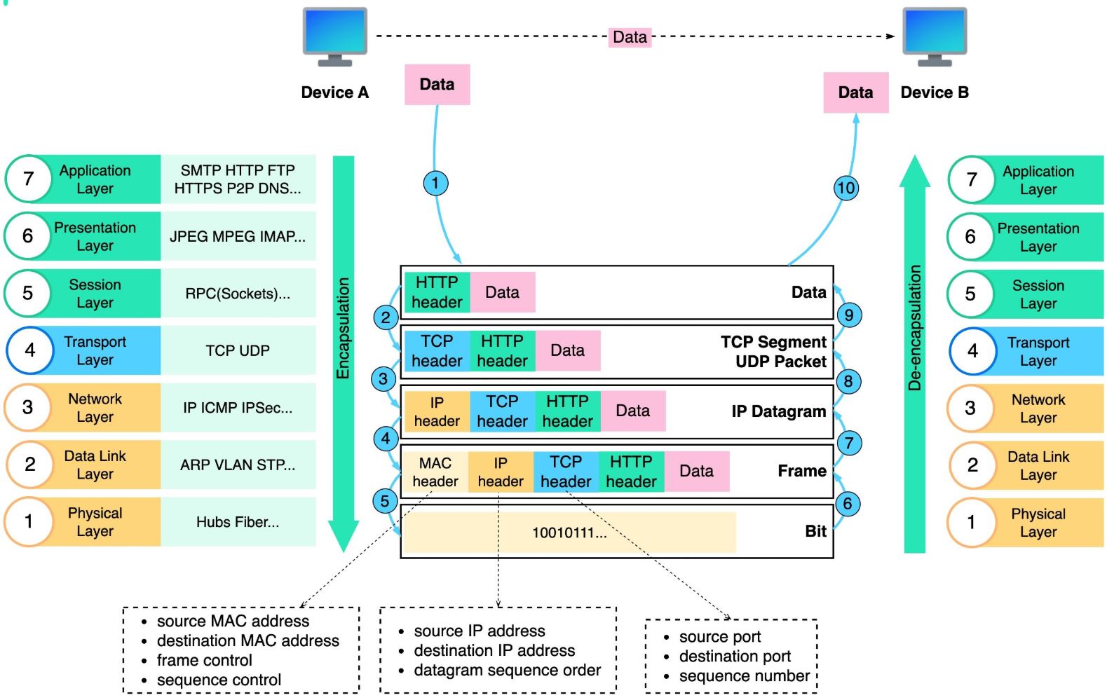
How is Data Sent Over the Network?
-
Step 1: When Device A sends data to Device B over the network via the HTTP protocol, it is first added an HTTP header at the application layer.
-
Step 2: Then a TCP or a UDP header is added to the data. It is encapsulated into TCP segments at the transport layer. The header contains the source port, destination port, and sequence number.
-
Step 3: The segments are then encapsulated with an IP header at the network layer. The IP header contains the source/destination IP addresses.
-
Step 4: The IP datagram is added a MAC header at the data link layer, with source/destination MAC addresses.
-
Step 5: The encapsulated frames are sent to the physical layer and sent over the network in binary bits.
-
Steps 6-10: When Device B receives the bits from the network, it performs the de-encapsulation process, which is a reverse processing of the encapsulation process. The headers are removed layer by layer, and eventually, Device B can read the data.
5.2 Different Layering Models
-
OSI Model (Open Systems Interconnection) - 7 Layers:
- The OSI model is a conceptual framework that standardizes the functions of a communication system into seven layers. This model helps to understand the complex processes involved in network communications.
-
TCP/IP Model - 5 Layers:
TCP/IP Model Explained
-
The TCP/IP model, also known as the Internet Protocol Suite, is a simplified model used to describe the Internet’s communication protocols. While it’s sometimes referred to as a 5-layer model, the most common 4-layer version is more widely used.
The 5 layers are:
- Physical Layer – OSI’s Physical Layer.
- Network Access Layer (Link Layer) – OSI’s Data Link Layer. It involves protocols like Ethernet and wireless communication.
- Internet Layer – Corresponds to OSI’s Network layer, responsible for routing and IP addressing (e.g., IP, ARP, ICMP).
- Transport Layer – Corresponds to OSI’s Transport layer and ensures reliable communication (e.g., TCP, UDP).
- Application Layer – Corresponds to OSI’s Application, Presentation, and Session layers, providing services like HTTP, FTP, DNS, etc.
-
-
Hybrid Models:
- These models combine elements from both OSI and TCP/IP layers. While OSI is a more theoretical framework, TCP/IP is more practical and commonly used. Hybrid models sometimes use a 5-layer approach, which includes an application layer, a transport layer, an internet layer, a data link layer, and a physical layer.
5.3 Why TCP/IP Model?
The TCP/IP model is the foundation of the internet, and we need it because:
-
Standardization:
- TCP/IP provides a universally accepted standard for communication between diverse devices and networks. This ensures all devices can talk to each other using common protocols and formats, enabling interoperability across the global internet.
-
Scalability:
- TCP/IP supports a vast number of devices and networks, making it possible to scale up to billions of devices (as seen with the growth of the internet).
-
Routing and Addressing:
- The IP (Internet Protocol) in the TCP/IP model is responsible for routing data packets to their correct destinations, based on IP addresses. It ensures that data sent over the internet reaches its intended recipient, even if it has to traverse multiple networks.
-
Reliability:
- TCP (Transmission Control Protocol) ensures reliable data transmission by managing packet sequencing, error detection, and retransmission, making sure that data arrives intact and in order.
-
Simplicity and Flexibility:
- TCP/IP is relatively simple and flexible, making it suitable for the diverse and constantly evolving network environment that the internet represents. It can work with both small-scale local networks and large-scale global networks.
-
Universal Adoption:
- The TCP/IP model is the de facto standard for networking protocols used on the internet. It is supported by nearly all modern devices and operating systems.
5.4 OSI 7-Layer Model vs TCP/IP Model
| Feature | OSI 7-Layer Model | TCP/IP Model |
|---|---|---|
| Number of Layers | 7 Layers (Physical, Data Link, Network, Transport, Session, Presentation, Application) | 4 Layers (Network Access, Internet, Transport, Application) |
| Layer Function | More detailed, with a separate layer for each function | Combines functions into fewer layers |
| Layer Name | Physical, Data Link, Network, Transport, Session, Presentation, Application | Network Access, Internet, Transport, Application |
| Layer Structure | Clearly distinguishes between Presentation, Session, and Application layers | Combines Presentation and Session into the Application Layer |
| Layer Complexity | More complex, with a focus on defining distinct roles for each layer | More streamlined, simpler approach |
| Development | Theoretical model designed to guide the development of networking technologies | Practical model built around the protocols used in real-world networking (specifically the internet) |
| Application Layer | Combines functions of application, session, and presentation layers | Combines functions of application, session, and presentation layers |
| Transport Layer | Responsible for end-to-end communication and flow control (TCP/UDP) | Same role, with a stronger emphasis on providing reliable data transmission through TCP |
| Network Layer | Defines routing and addressing (IP, routers) | Provides routing and addressing (IP) for packet delivery |
| Session Layer | Manages sessions or dialogues between applications (e.g., NetBIOS) | Integrated into the Application Layer |
| Presentation Layer | Handles data translation, encryption, and compression | Integrated into the Application Layer |
| Communication Protocols | Defines protocols like HTTP, FTP, SMTP, POP, IMAP, etc. | Focused on TCP, UDP, and IP protocols |
| Use in the Internet | More of a conceptual framework, rarely implemented as-is | Directly implemented in real-world internet protocols |
Key Differences Between OSI and TCP/IP Models
-
Number of Layers:
- The OSI model has 7 layers, providing a more detailed structure for networking tasks, while the TCP/IP model uses 4 layers, simplifying the model and combining some of the OSI layers into a single layer.
-
Purpose:
- The OSI model is a theoretical model designed for understanding and teaching networking concepts. In contrast, the TCP/IP model is a practical model that is directly implemented in the communication protocols used on the internet.
-
Layer Responsibilities:
- The OSI model clearly distinguishes the roles of Session and Presentation layers, whereas the TCP/IP model combines these into the Application layer.
-
Protocol Flexibility:
- OSI is more of a conceptual guide, with each layer potentially using different protocols, while TCP/IP is protocol-centric and defines specific protocols (TCP, IP, UDP, etc.) for each layer.
-
Adoption:
- TCP/IP is the standard model used on the internet today, whereas the OSI model is primarily used for educational purposes and theoretical understanding.
5.5 OSI 7 Layer Model Implementation
While the OSI 7-layer model is primarily theoretical and not directly implemented in real-world networking protocols, it is still widely used as a conceptual framework for understanding and teaching how network protocols interact. It offers a structured approach for analyzing and troubleshooting network communication by breaking it down into manageable layers.
5.5.1 Real-World Use Cases of OSI 7-Layer Model
-
Educational and Training Purposes:
- The OSI model is heavily used in networking education to teach students and professionals about networking concepts. It provides a clear, logical way to approach networking and makes it easier to understand the various functions of different protocols at each layer.
- For example, Cisco Networking Academy and other training programs use the OSI model to help learners understand how devices communicate, how data flows through a network, and where potential issues might arise.
-
Network Troubleshooting:
- The OSI model helps network engineers troubleshoot network issues by providing a systematic way to isolate where problems might be occurring. For example:
- If a user cannot access a website, the technician might use the OSI model to check whether the issue is related to physical connectivity (Layer 1), data transmission (Layer 2), or addressing and routing (Layer 3).
- The “OSI Troubleshooting Approach” is a common method used in network support to help pinpoint problems step by step, starting from the Physical Layer up to the Application Layer.
- The OSI model helps network engineers troubleshoot network issues by providing a systematic way to isolate where problems might be occurring. For example:
-
Network Protocol Design:
- The OSI model served as inspiration for designing modern network protocols, especially in the context of layering concepts.
- The TCP/IP model (which is the foundation of the internet) was influenced by OSI’s layering structure, though it simplifies the model into 4 layers.
- Many network protocols, such as SMTP (email), HTTP (web browsing), FTP (file transfer), etc., correspond to specific layers in the OSI model, and the OSI model helps categorize their role in network communication.
- The OSI model served as inspiration for designing modern network protocols, especially in the context of layering concepts.
-
Developing and Analyzing Networking Standards:
- The OSI model provides a standard framework that can be used by industry groups and standardization bodies like IETF (Internet Engineering Task Force), IEEE, and ISO to develop new protocols or improve existing ones.
- The Internet Protocol Suite (TCP/IP), though not an exact implementation of OSI, aligns with the concept of layering from the OSI model, helping standardize how devices communicate over the internet.
-
Software Development:
- Software developers, particularly those working on network-related applications, often use the OSI model as a reference to ensure that their software correctly implements network protocols at various layers.
- Network simulation software, like Packet Tracer or Wireshark, uses OSI layers to display the communication process. Tools like Wireshark allow users to capture and analyze packets based on the OSI model, breaking down each layer of the packet for detailed inspection.
-
Firewalls and Network Security:
- In network security, the OSI model helps to define security measures at each layer. Firewalls, for instance, often work at various layers (e.g., filtering traffic based on IP addresses at Layer 3, or examining HTTP requests at Layer 7).
- Understanding which layer an attack occurs at is crucial for identifying the best defensive strategies. For example, DDoS (Distributed Denial of Service) attacks may target the network layer (Layer 3), while phishing attacks would target the application layer (Layer 7).
-
Quality of Service (QoS) Implementation:
- QoS protocols often refer to the OSI model to define how traffic should be managed at various layers. For example, QoS mechanisms can prioritize traffic at the transport layer (e.g., TCP/UDP), ensure bandwidth allocation at the network layer, and adjust packet flow at the data link layer to optimize network performance.
5.5.2 Examples of Use Cases Based on OSI Layers
-
Layer 1 (Physical Layer): Ensures that physical transmission media (cables, wireless signals) are properly functioning. Use cases might include checking physical connections in a network (e.g., damaged cables or faulty ports).
-
Layer 2 (Data Link Layer): Includes protocols such as Ethernet and Wi-Fi, which ensure that data is transmitted error-free between devices on the same network. For example, MAC address filtering and Ethernet switch management are functions of this layer.
-
Layer 3 (Network Layer): Involves routing and IP addressing. This layer is crucial for ensuring devices in different networks can communicate. Use cases include:
- IP addressing (assigning unique addresses to devices).
- Routing protocols like OSPF and BGP that manage traffic between different networks.
-
Layer 4 (Transport Layer): Ensures reliable communication between devices. TCP and UDP are key protocols here. Use cases include:
- TCP connections to guarantee data delivery.
- UDP for streaming services (where speed is prioritized over reliability).
-
Layer 5 (Session Layer): Manages sessions or dialogues between applications. An example is:
- NetBIOS or RPC (Remote Procedure Call) protocols that allow applications to establish, maintain, and terminate communication sessions.
-
Layer 6 (Presentation Layer): Handles data formatting, encryption, and compression. An example is:
- SSL/TLS encryption used in HTTPS for secure communication between web browsers and servers.
-
Layer 7 (Application Layer): This is where end-user applications interact with the network. Examples include:
- HTTP (Hypertext Transfer Protocol) for web browsing.
- SMTP for email communication.
6. Internet
The Internet is a massive network of networks that connects millions of private, public, academic, business, and government networks. It allows devices (computers, smartphones, servers, etc.) to communicate and exchange data using a common set of protocols, primarily TCP/IP (Transmission Control Protocol/Internet Protocol).
WWW (World Wide Web)
The Internet and the World Wide Web (WWW) are often used interchangeably, but they are not the same thing. They are related concepts, but they serve different purposes and operate in different ways. Here’s a detailed explanation of the differences between the Internet and the World Wide Web:
Internet
The Internet is a global network of interconnected computers and devices that communicate with each other using standardized protocols like TCP/IP.
It is the infrastructure that enables communication and data exchange across the world.
World Wide Web (WWW)
The World Wide Web is a collection of interconnected documents and resources (web pages, images, videos, etc.) that are accessed over the Internet using HTTP/HTTPS.
It is a service that runs on top of the Internet.
6.1. Purpose
- Internet:
- The Internet is the underlying network that enables various services, including:
- File transfer (FTP)
- Online gaming
- Voice over IP (VoIP)
- Streaming
- And, of course, the World Wide Web.
- The Internet is the underlying network that enables various services, including:
- World Wide Web:
- The World Wide Web is specifically designed for accessing and sharing information through web pages and hyperlinks.
- It is one of many services that run on the Internet.
6.2 How They Work
- Internet:
- The Internet is a physical and logical infrastructure that connects devices using:
- Hardware: Routers, switches, cables, satellites, etc.
- Protocols: TCP/IP, DNS, UDP, etc.
- Data is transmitted in the form of packets across networks.
- The Internet is a physical and logical infrastructure that connects devices using:
- World Wide Web:
- The World Wide Web is a system of interlinked hypertext documents accessed via web browsers.
- It uses:
- HTTP/HTTPS: Protocols for transferring web pages.
- HTML: Language for creating web pages.
- URLs: Addresses for locating resources on the web.
6.3 Key Components
- Internet:
- Devices: Computers, smartphones, servers, routers, etc.
- Protocols: TCP/IP, DNS, FTP, SMTP, etc.
- Infrastructure: ISPs, data centers, undersea cables, satellites, etc.
- World Wide Web:
- Web browsers: Chrome, Firefox, Safari, etc.
- Web servers: Host websites and serve web pages.
- Protocols: HTTP/HTTPS.
- Languages: HTML, CSS, JavaScript.
6.4 Historical Context
- Internet:
- The Internet originated in the 1960s as ARPANET, a project funded by the U.S. Department of Defense.
- It was designed to create a decentralized network that could survive partial outages.
- World Wide Web:
- The World Wide Web was invented in 1989 by Tim Berners-Lee at CERN.
- It was designed to make it easier for scientists to share and access documents.
6.5 Scope
- Internet:
- The Internet is a broader concept that encompasses all forms of online communication and services.
- It includes email, file transfer, online gaming, streaming, and more.
- World Wide Web:
- The World Wide Web is a subset of the Internet focused on accessing and sharing information through web pages.
6.6 Examples
- Internet:
- Sending an email.
- Transferring files using FTP.
- Making a VoIP call.
- Playing an online game.
- World Wide Web:
- Browsing a website (e.g.,
www.google.com). - Watching a video on YouTube.
- Reading an article on Wikipedia.
- Browsing a website (e.g.,
6.7 Visualization
- Internet:
- Think of the Internet as the highway system that connects cities and towns.
- World Wide Web:
- Think of the World Wide Web as the delivery trucks that use the highways to transport goods (web pages, videos, etc.).
6.8 Summary of Differences
| Feature | Internet | World Wide Web (WWW) |
|---|---|---|
| Definition | Global network of interconnected devices. | Collection of interlinked documents and resources. |
| Purpose | Enables communication and data exchange. | Accesses and shares information via web pages. |
| Key Components | Routers, switches, TCP/IP, DNS, etc. | Web browsers, HTTP/HTTPS, HTML, URLs, etc. |
| Scope | Broader (includes email, FTP, gaming, etc.). | Subset of the Internet (focused on web pages). |
| Invented | 1960s (ARPANET). | 1989 (Tim Berners-Lee). |
| Example | Sending an email, online gaming. | Browsing a website, watching a video. |
7. Networking Topologies
Networking topologies refer to the physical or logical layout of devices and connections in a computer network. It defines how devices (nodes) are arranged and how they communicate with each other. The topology affects network performance, scalability, reliability, and management. Here are the most common types of networking topologies:
7.1 Bus Topology
- Description: In a bus topology, all devices are connected to a single central cable (the bus), which carries the data signals. Each device sends data along the bus, and the data is available to all other devices.
- Characteristics:
- Simple and inexpensive to implement.
- Data collisions can occur if multiple devices send data at the same time.
- If the central bus cable fails, the entire network is down.
- Example: Older Ethernet networks often used bus topology.
7.2 Star Topology
- Description: In a star topology, all devices are connected to a central device, such as a hub or switch. Each device communicates through the central device.
- Characteristics:
- Easy to install and manage.
- If the central device fails, the whole network is affected.
- Minimal data collisions as devices communicate via the central hub.
- Example: Modern Ethernet networks, Wi-Fi access points.
7.3 Ring Topology
- Description: In a ring topology, devices are connected in a circular fashion, and data travels in one direction around the ring from one device to the next until it reaches its destination.
- Characteristics:
- Data travels in a continuous loop, reducing data collisions.
- Failure in one device or connection can disrupt the entire network.
- Each device in the network acts as a repeater to amplify the signal.
- Example: Older Token Ring networks.
7.4 Mesh Topology
- Description: In a mesh topology, every device is connected to every other device, creating multiple paths for data to travel. There are two types:
- Full Mesh: Every device is connected to every other device.
- Partial Mesh: Some devices are connected to every other device, but not all.
- Characteristics:
- Highly redundant, fault-tolerant, and reliable because there are multiple communication paths.
- Expensive and complex to implement due to the large number of connections.
- Example: Internet backbone networks often use mesh topology for redundancy.
7.5 Hybrid Topology
- Description: A hybrid topology combines two or more different types of topologies in one network. For example, a network might use a combination of star and bus topologies.
- Characteristics:
- Flexible and scalable, allowing for easy expansion.
- Can combine the strengths of different topologies.
- Example: A large corporate network might use star topology for individual departments and a bus topology for connecting them.
7.6 Tree Topology (or Hierarchical Topology)
- Description: Tree topology is a combination of star and bus topologies. It uses a central root node and branches out to other nodes, creating a hierarchical structure.
- Characteristics:
- Scalable and easy to expand.
- Failure in a branch can disrupt communication for that branch, but not the entire network.
- Example: Large campus networks, where buildings or departments are interconnected in a hierarchical manner.
7.8 Table of Common Topologies
| Topology | Description | Advantages | Disadvantages |
|---|---|---|---|
| Bus | Single central cable connects all devices. | Simple and cost-effective. | Can be slow with high traffic, single point of failure. |
| Star | All devices are connected to a central hub/switch. | Easy to manage, less collision. | Hub failure brings down the network. |
| Ring | Devices are connected in a circle; data travels in one direction. | Simple, predictable data path. | One device failure disrupts the entire network. |
| Mesh | Devices are interconnected with multiple paths. | Highly fault-tolerant and reliable. | Expensive, complex to set up. |
| Hybrid | Combination of two or more topologies. | Flexible, scalable. | Complexity increases as more topologies are combined. |
| Tree | Hierarchical, combining star and bus. | Scalable, easy to expand. | Branch failures can isolate parts of the network. |
8. Standards in Measuring Data Sizes
In networking and computing, there are two common standards for measuring data sizes: Binary (Base 2) and Decimal (Base 10). These standards define how we convert between units such as bits, bytes, kilobytes, megabytes, etc.
8.1 Binary (Base 2) Standard (IEC Standard)
- In the binary system, each unit is based on powers of 2. This standard is widely used in computing (especially in memory and storage contexts).
- 1 byte = 8 bits.
- The conversion follows powers of 2:
- 1 kilobyte (KB) = 1,024 bytes.
- 1 megabyte (MB) = 1,024 KB = 1,048,576 bytes.
- 1 gigabyte (GB) = 1,024 MB = 1,073,741,824 bytes.
- 1 terabyte (TB) = 1,024 GB = 1,099,511,627,776 bytes.
This system is used by most computer hardware, operating systems, and software when dealing with memory sizes and disk storage.
8.2 Decimal (Base 10) Standard (SI Standard)
- The decimal system is used in contexts where metric-based measurements are more common, such as networking and data transmission rates (e.g., internet speeds).
- In this standard, each unit is based on powers of 10:
- 1 byte = 8 bits.
- 1 kilobyte (KB) = 1,000 bytes.
- 1 megabyte (MB) = 1,000 KB = 1,000,000 bytes.
- 1 gigabyte (GB) = 1,000 MB = 1,000,000,000 bytes.
- 1 terabyte (TB) = 1,000 GB = 1,000,000,000,000 bytes.
This system is used in networking speeds (such as Mbps or Gbps), disk drives, and in general consumer electronics.
8.3 Example of Conversion
-
Binary Standard:
- 1 KB = 1,024 bytes.
- 1 MB = 1,024 KB = 1,048,576 bytes.
-
Decimal Standard:
- 1 KB = 1,000 bytes.
- 1 MB = 1,000 KB = 1,000,000 bytes.
Practical Example
If a network connection has a speed of 1 Gbps:
- In the Decimal (SI) system, 1 Gbps = 1,000 Mbps.
- In the Binary (IEC) system, 1 Gbps = 1,024 Mbps.